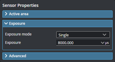
Exposure
Exposure determines the duration of camera and light-source on-time (or pulse width), given in microseconds (µs). Longer exposures can be helpful to detect light on dark or distant surfaces, but increasing exposure time decreases the maximum speed. Different target surfaces may require different exposures for optimal results. In general, shiny and mirror-like surfaces require a short pulse width and low-gloss surfaces a high pulse width.
Sensors provide two or three exposure modes, depending on the model, for the flexibility needed to scan different types of target surfaces.
To properly set exposure, you can acquire scan data in Image mode, and examine the resulting image to confirm whether the features or flaws you need to measure will be well presented in the scan data. For more information on Image mode and the information it provides for configuring exposure, see Image Mode.
You configure exposure in the Exposure panel on the Inspect > Scan page, in the Sensor Properties section.

|
When exposure is set to Dynamic or Multiple, additional parameters are displayed. |
| Exposure Mode | Description |
|---|---|
| Single | Uses a single exposure duration for each frame. Use this when the surface is roughly uniform and is the same for all targets. For more information, see Single Exposure. |
| Multiple | Uses multiple exposures to create a single scan. Used when the target surface has a varying reflectance within a single scan. For more information, see Multiple Exposure. |
When the sensor is set to Image mode (see Scan Modes and Intensity), a Video pattern type parameter is available. (When this parameter is set to Scan Sequence, a Video pattern Index parameter is also available.)
| Parameter | Description |
|---|---|
|
Pattern |
One of the following: Default: The default projector pattern. Scan Sequence: Enables the Pattern Index parameter (see below). Projector Off: Turns the projector off during acquisition for customers who want to capture video images using external lighting. Focus: A special pattern available on Gocator 3506 sensors used to help focus the sensor. For more information, see Using the Focus Pattern (Gocator 3506 only). |
|
Pattern Index |
The index of the pattern sequence to display. Choose the pattern that produces the best data. The indices represent Phase Pattern Sequences, followed by Stripe Pattern Sequences in reverse order. The lower indices are the higher frequency phase code patterns, and the higher indices are the lower frequency binary patterns. Index 1 [Phase Pattern Sequence Image 5]: Highest frequency sinusoid. Index 2 [Phase Pattern Sequence Image 4] [...] Index 5 [Phase Pattern Sequence Image 1]: Lowest frequency sinusoid. Index 6 [Stripe Pattern Sequence Image 7]: Highest bar count. Index 7 [Stripe Pattern Sequence Image 6] [...] Index 12 [Stripe Pattern Sequence Image 1]: Lowest bar count) Index 13 [Reference Image 1] |
Using the Focus Pattern (Gocator 3506 only)
On Gocator 3506 sensors, you can use a special "line" focus pattern to aid in focusing the sensor. A focused sensor produces more accurate scans, which in turn results in more reliable measurements.
To use the focus pattern:
| 1. | Place a representative target in view of the sensor. |
The target surface should be similar to the material that will normally be measured.
| 2. | Go to the Scan page and choose Video mode. |
| 3. | Expand the Sensor panel by clicking on the panel header or the  button. button. |
| 4. | Click the Exposure tab. |
| 5. | In Pattern, choose Focus. |
A vertical line pattern is projected onto the surface (see next).
| 6. | Move the sensor up and down until the dark lines are as sharp as possible. |
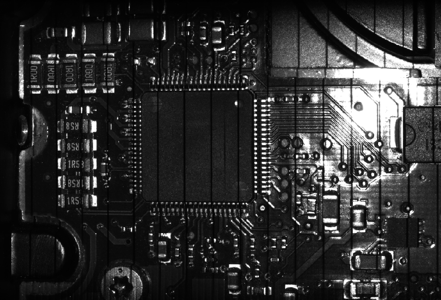
In the following image, the vertical lines are blurry:
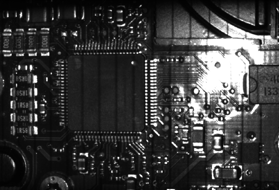
After focusing, the lines are more sharply defined: