Ring Layouts (Surface Align Ring Tool)
The Surface Align Ring tool performs a high-accuracy alignment of G2 multi-sensor ring layouts, using recorded data, and using a double-sided truncated pyramid alignment target that you must fabricate (for more information, see Alignment Target). The tool is only intended for use with these sensors and system layouts. Unlike alignment using the Alignment panel on the Scan page, the tool determines the X angle rotation (for information on coordinate systems, see Profile Output), giving you a full six degrees of freedom. This method of alignment will produce higher accuracy scans, and allows for higher scan rates, due to the use of a different data-merging algorithm. The tool saves the transformations for each sensor in an XML initialization file.

|
Performing alignment using the Surface Align Ring or Surface Align Wide tools (which results in 6 degrees of freedom) involves considerable setup effort. First, the 6 DoF alignment targets are more difficult to manufacture than an alignment bar and require a very high degree of accuracy; 3D printed alignment targets are not usually sufficiently accurate. Second, the alignment tools have many parameters that must be properly configured to successfully perform an alignment. |

|
You only need to use this tool to produce a configuration file containing the sensor transformations that Surface Mesh needs to merge scan data. For more information, see Surface Mesh. |
|
|
This tool requires acceleration (either by a PC-based application or by GoMax). For more information, see Running GoPxL on a Windows PC. |
|
|
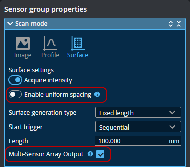
Before scanning the alignment target, remember to uncheck Enable uniform spacing in the Scan mode section on the Scan page. Also enable Multi-Sensor Array Output.
|
|
|
Sensors must not previously have been aligned using the alignment routine on the System > Alignment page. This is indicated by "Not Aligned" on that page. If necessary, click Clear Alignment.
|
|
|
Typically, you will use separate jobs for the alignment procedure and for production measurement. |
Note that in order to perform scans in production, you must use the Surface Mesh tool (loading the configuration file created by this tool) to stitch the scans from the individual sensors into Mesh data; for more information on the Surface Mesh tool, see Surface Mesh. You can then either perform measurements directly on the Mesh data using the Mesh measurement tools (see Mesh Measurement) or you can extract Surface data from the Mesh data and apply any built-in or custom GDK-based Surface tools to the resulting data (see Surface Measurement).
Alignment Target
This alignment tool requires the use of a double-sided truncated pyramid alignment target. You can find CAD files for this type of target under Tools\Alignment CAD\Double Sided Pyramid in the Utilities package (for example, 14405-x.x.xx.xx_SOFTWARE_GO_Utilities.zip, available on LMI's Product Downloads page). Note that you should adapt the size of the alignment target to the size of the sensors in your system: the target should be scaled so it fills most of the field of view of a sensor.

Example dimensions for mid-size FOV sensors.
After configuring Surface Align Ring (see below), you must check the Enable Processing checkbox to produce the XML initialization file. After the tool has finished processing the data and has successfully aligned the sensors, it produces the XML file you load into a Surface Mesh tool. Note that the tool actually creates two copies of the initialization file: one called Configuration.xml, and another with a date-time stamp in its name, such as Configuration_20240531_120452.xml. The tool also creates Difference Surface and Segmentation Surface data outputs that you can use to assess the quality of the alignment.
Note that after using this tool, on the Alignment panel on the Scan page, GoPxL indicates that the sensors are unaligned. This is normal.
Alignment Target and Setup
The following requirements should be satisfied for best results:
-
3D printed targets are not recommended, as they may lack the required accuracy. Ideally, you should machine the alignment target.
- Make sure the alignment target surface is not too shiny or too dark to be scanned. A diffuse surface is best.
-
Maximize the size: The target should fill the scan volume of each sensor but not extend past the field of view of the sensors.
-
Edges do not need to be perfectly sharp: The alignment tool performs a plane fit to points within the planar surfaces and excludes data close to the edges.
-
No planar surfaces other than those on the alignment target should be visible in the scan results. For example, do not scan the target set on a flat surface such that the surface is included in the scan results.
-
Each sensor in the system must be able to properly scan a minimum of 5 planar surfaces of the alignment target. If necessary, rotate the alignment target to ensure this.
-
Ensure the ratio of X and Y scan resolutions does not exceed 1:5. For more information on setting the X resolution, see Uniform Spacing. For information on setting Y resolution, see Triggers.
Alignment Procedure
The following provides the steps involved in performing a high-accuracy, tool-based alignment.
|
|
The following assumes you are scanning the alignment target using unaccelerated sensors and then uploading the recording to a PC instance of GoPxL. The procedure for doing this with accelerated sensors is similar. |
To perform the alignment:
| 1. | Fabricate an alignment target appropriate for your system (wide layout versus ring layout). |
For details on the alignment target, see Alignment Target.
| 2. | If you have not already done so, set up and configure the multi-sensor system. |
The following sections describe installing, setting up, and configuring a system:
Sensor Management and Maintenance
When configuring the system's layout, put all sensors in the top row, regardless of their physical position.
Scan - Configuring Acquisition
| 3. | Make sure to do the following. |
Disable Uniform Spacing and enable Multi-Sensor Array Output in the Scan mode section on the Inspect > Scan page.
Sensors must not previously have been aligned using the alignment routine on the System > Alignment page. This is indicated by "Not Aligned" on that page. If you see "Aligned" here, click Clear Alignment,

|
|
Although you can scan the alignment target without acceleration, you must perform the alignment using PC-based acceleration (for more information, see Running GoPxL on a Windows PC). Because starting acceleration after having performed a scan clears scan data from a sensor, if you are going to perform alignment on-sensor, you should start acceleration before continuing. You can also optionally download the scan data and perform the alignment on the scanned target using GoPxL on Windows. For more information, see Recording and Working with Scan Data (Toolbar). |
| 4. | If any sensors are installed in a "reversed" orientation (that is, such that the conveyor moves in the same direction as the sensor's positive Y axis), be sure to set the sensor's layout to Reverse. |
| 5. | Enable recording by clicking the Record button to the right above the data viewer. |
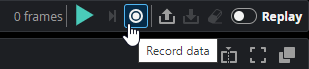
GoPxL shows recording is enabled.

| 6. | Start the transport system and then perform a scan of the alignment target. |
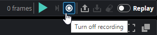
| 7. | Turn off recording. |
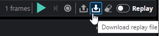
| 8. | Download the recording and make note of the downloaded file's location. |
| 9. | Launch a PC instance of GoPxL. |
For more information, see Running GoPxL on a Windows PC.
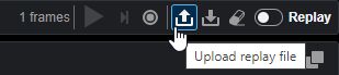
| 10. | Upload the recording of the alignment target in the PC instance. |
| 11. | On the Inspect > Tools page, add a Surface Align Ring tool. |
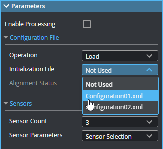
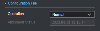
| 12. | (Optional) If you have a previously saved configuration file, expand the Configuration File section and choose Load from the Operation drop-down, load that file, and go to step 16. |
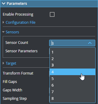
| 13. | In the expandable Sensors section, set Sensor Count to the number of sensors in the system. |
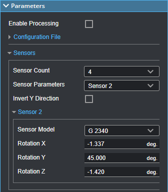
| 14. | Under Sensor Parameters, select the sensors, one by one, and configure the parameters related to the sensor's position. |
For more information, see Sensor Parameters.
| 15. | Expand the Target section and configure the parameters related to the alignment target. |
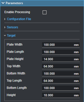
For more information, see Double-Sided Pyramid Target Parameters.
| 16. | Configure the tool's remaining parameters (see Parameters). |
| 17. | Enable any measurements or the Processed Surface outputs if needed. |
These outputs can be useful for diagnostics.
| 18. | Check the Enable Processing checkbox. |
The tool processes the scan data, using the provided sensor positions or rotations and alignment target characteristics, and saves a configuration file to C:/GoTools/SurfaceAlign. If the alignment process succeeds, the Alignment Status field in the Configuration File section displays the time and date of the alignment.
You must load the resulting configuration file in a Surface Mesh tool, typically in a separate job, which transforms the multi-sensor scan data into a common coordinate system and produces a Mesh output. You can then apply other measurement tools to the merged scan data. For more information on the merging tool, see Surface Mesh.
Inputs
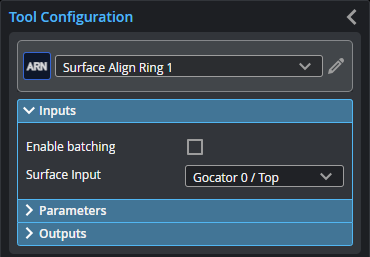
You configure the tool's inputs in the expandable Inputs section.
| Name | Description |
|---|---|
| Enable Batching |
Leave this setting unchecked. |
|
Surface Input |
The data the tool applies measurements to or processes. |
Parameters
You configure the tool's parameters in the expandable Parameters section.
| Parameter | Description |
|---|---|
|
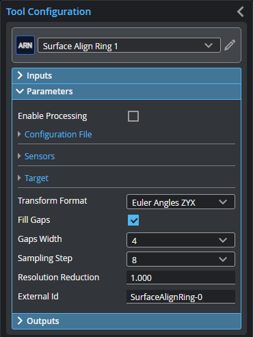
Enable Processing |
Starts the alignment procedure. Make sure to properly configure the tool before enabling this option. Disable it after performing the alignment; otherwise, the tool will continue performing the alignment on new frames of data, which will have an impact on performance. (Ideally, you should use a separate job for the alignment procedure.) |
| Configuration File | An expandable section that contains file-related parameters. |
|
Operation |
Actions that apply to the tool's configuration files. One of the following:
|
| Sensors | An expandable section that contains sensor related parameters. |
|
Sensor Count |
Indicates the number of sensors in the system. |
|
Sensor Parameters |
A drop-down that display the settings of the selected sensor. For descriptions of the individual sensor parameters used for the alignment, see Sensor Parameters. |
| Invert Y Direction |
Converts from a left-handed coordinate system to a right-handed coordinate system. Enable this only if the sensor is mounted in a reverse position and identified as Reversed in the Add & Manage Sensor Group dialog in the System > Design page. This setting applies to all sensors. |
|
Target |
An expandable section that contains parameters related to the double-sided pyramid target's specifications. For descriptions of the pyramid parameters, see Double-Sided Pyramid Target Parameters. |
|
Transform Format |
The transformation format the tool uses. Choosing a different format may be useful if you need to compare what the sensors detect to the transformation format used in your CAD package, for example. The setting does not affect alignment. One of the following:
|
|
Fill Gaps |
When this option is enabled, the tool displays a Gaps Width parameter (see below). |
|
Gaps Width |
The kernel the tool uses to initially calculate the surface normal required for alignment. Typically, a value of 4 works for most applications. If alignment fails and you can't track down the issue, try a different value. |
|
Sampling Step |
The step in data points in both directions with which the surface is sampled. Choosing a higher sampling step reduces the processing time the tool requires, but reduces fit accuracy. Typically, you will want to use as low a sampling step as possible; use a high sampling step only for initial testing purposes. |
|
Resolution Reduction |
Reduces the lateral resolution of the heightmap to reduce processing time. |
|
External ID |
The external ID of the tool that appears in GoHMI Designer. For more information, see GoHMI and GoHMI Designer. |
The following image indicates which parameters (see the table below) correspond to which parts of the alignment target.

Outputs
Most tools provide measurements, geometric features, or data as outputs.
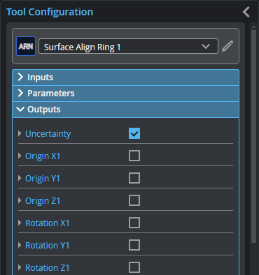
| Measurement |
|---|
|
Uncertainty Alignment uncertainty (an indicator of alignment quality). |
|
Origin X{n} Origin Y{n} Origin Z{n} The X, Y, and Z transformations calculated for sensor {n}. |
|
Rotation X{n} Rotation Y{n} Rotation Z{n} The X, Y, and Z angle transformations calculated for sensor {n}. |
|
|
Enable Processing must be checked to view the following diagnostic data outputs. |
