Profile Strip
The Strip tool returns various measurements related to a strip, such as its X and Z positions, width, and height.
The tool lets you optionally set an index to return the measurements of a specific strip when more than one is visible in the region of interest. If you need to return multiple strips from a profile, add a Profile Strip tool for each strip, configure it to represent the desired strip, and set its Selection Index parameter to the desired strip (0-based index).
The Strip tool uses a complex feature-locating algorithm to find a strip and then return measurements. For a detailed explanation of the algorithm, see Strip Algorithm. The behavior of the algorithm can be adjusted by changing the tool's parameters.
For information on adding, managing, and removing tools, as well as detailed descriptions of settings common to most tools, see Tool Configuration.
Inputs
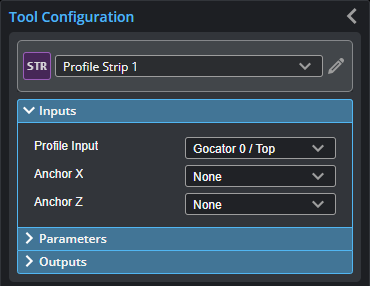
You configure the tool's inputs in the expandable Inputs section.

|
To use a measurement as an anchor, it must be enabled and properly configured in the tool providing the anchor. For more information on anchoring, see Measurement Anchoring. |
| Name | Description |
|---|---|
|
Profile Input |
The data the tool applies measurements to or processes. |
|
Anchor X or Anchor Z |
The X or Z measurement of another tool that this tool uses as a positional anchor. Positional anchors are optional. |
Parameters
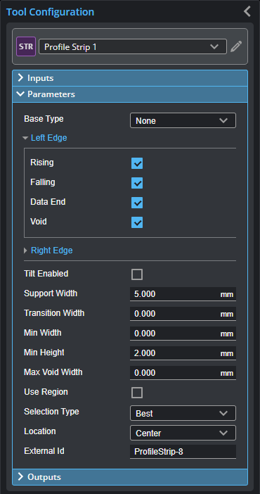
You configure the tool's parameters in the expandable Parameters section.
| Parameter | Description |
|---|---|
|
Base Type |
Affects detection of rising and falling edges.
When Base Type is set to Flat, both strip (raised area) and base support regions are needed. When set to None, only a point that deviates from a smooth strip support region is needed to find a rising or falling edge. |
|
Left Edge Right Edge |
Specifies the features that will be considered as the strip's left and right edges. You can select more than one condition. Rising - Rising edge detected based on the strip edge parameters. Falling - Falling edge detected based on the strip edge parameters. Data end - First valid profile data point in the measurement region. Void - Gap in the data that is larger than the maximum void threshold. Gaps connected to the measurement region's boundary are not considered as a void. For the definitions of these conditions, see Strip Start and Terminate Conditions. |
|
Tilt Enabled |
Enables and disables tilt correction. The strip may be tilted with respect to the sensor's coordinate X axis. This can be caused by conveyor vibration. If the Tilt option is enabled, the tool will report the width and height measurements, corrected by the tilt angle of the strip.
|
|
Support Width |
Specifies the width of the region around the edges from which the data is used to calculate the step change. For information on how this parameter is used by different base types, see Strip Step Edge Definitions. |
|
Transition Width |
Specifies the nominal width needed to make the transition from the base to the strip. For information on how this parameter is used by different base types, see Strip Step Edge Definitions. |
|
Min Width |
Specifies the minimum width for a strip to be considered valid. |
|
Min Height |
Specifies the minimum deviation from the strip base. For information on how this parameter is used by different base types, see Strip Step Edge Definitions. |
|
Max Void Width |
The maximum width of missing data allowed for the data to be considered as part of a strip when Void is selected in the Left or Right parameter. This value must be smaller than the edge Support Width.
When occlusion and exposure causes data drops, use a gap filling filter in a Profile Filter tool to fill the gaps; for more information, see Profile Filter. |
|
Use Region |
When enabled, displays Region parameters (see below). When disabled, the tool uses all data. |
|
Region |
The measurement region defines the region in which to search for the strip. If possible, the region should be made large enough to cover the base on the left and right sides of the strip.
For more information, see Regions. |
|
Location (Strip Height, Strip X, and Strip Z measurements only) |
Specifies the strip position from which the measurements are performed. Left - Left edge of the strip. Right - Right edge of the strip. Center - Center of the strip. |
|
Selection Type |
Specifies how a strip is selected when there are multiple strips within the measurement area. Best - The widest strip. Index Left - 0-based strip index, counting from left to right. Index Right - 0-based strip index, counting from right to left. |
|
Index |
0-based strip index. Only displayed when Selection Type is set to an "Index" option. |
|
External ID |
The external ID of the tool that appears in GoHMI Designer. For more information, see GoHMI and GoHMI Designer. |


Outputs
All tools provide measurements, geometric features, or data as outputs.
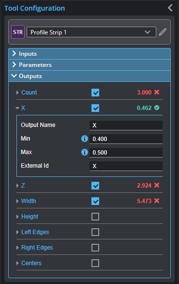
Outputs section with a measurement expanded to show user-configurable decision min/max fields and an external ID
You configure the Min and Max parameters by expanding the measurement in the Outputs section. In order for a measurement to return a Pass decision, the measurement must be between maximum and minimum values; the range is inclusive.
| Measurement | Illustration |
|---|---|
|
Count The number of strips. |
|
|
X, Z Measures the X and Z position, respectively, of a strip. |
|
|
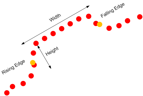
Width Measures the width of a strip. |
|
|
Height Measures the height of a strip. |
|


| Type | Description |
|---|---|
|
Left Edges Right Edges Centers |
Arrays of Point geometric features representing the left edges, right edges, and centers of all strips, from left to right. |
Strip Algorithm
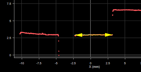
A strip is a flat region bounded on the left and on the right by edges. The Strip tool can measure the edge positions, width, and height of a strip. The Strip tool assumes that regions outside the strip, referred to as the base regions (Region A and D below), deviate in height from the start and end parts of a strip (Region B and C).
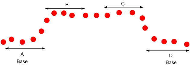
When the target is sitting on the surface, the base is lower than the strip (as shown above). Alternatively for a groove the base is above the strip surface. The base could be missing when the target is hanging in the air or the surface holding the target falls outside the sensor's active area. You can control the base type in the measurement panel.
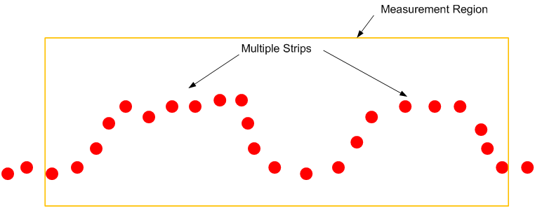
The Strip tool can detect multiple strips. You can select a region of interest, referred to as the measurement region, from which the algorithm search for multiple strips.
Strip Start and Terminate Conditions
The Strip tool allows you to define how a strip starts and ends. The Left Edge parameter controls how a strip starts and the Right Edge parameter controls how a strip ends.
| Condition | Description |
|---|---|
|
Rising |
Rising step edge detected based on the strip edge parameters. For details on how the step edge is detected, Strip Step Edge Definitions. |
|
Falling |
Falling step edge detected based on the strip edge parameters. For details on how the step edge is detected, Strip Step Edge Definitions. |
|
Data end |
The first (for the left edge) or the last (for the right edge) valid profile data point in the measurement region.
|
|
Void |
Gaps in the data that are larger than the maximum void threshold.
Gaps at the ends of the measurement region's boundary are not considered as a void.
|


The following examples show how the parameters affect the strip detection in different scenarios.
| Condition | Example |
|---|---|
|
Left: Rising, data end, void Right: Falling, data end, void |
|
|
Left: Rising, void Right: Falling, void |
|
|
Left: Rising Right: Data end, void |
|
|
Left: Data end, void Right: Falling |
|
|
Left: Falling Right: Rising |
|


Strip Step Edge Definitions
The Strip tool detects step edges based on the parameters Base Type, Edge Transition Width, Edge Support Width, and Minimum Edge Height.
When Base Type is set to Flat, the regions around the edges are visible and the edge positions are between the base and the strip surface.
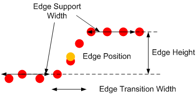
The Minimum Edge Height parameter defines the size of the step edge. The Edge Transition Width parameter specifies the nominal width of the transition, from the base to the strip surface.
The Edge Support Width parameter defines the width of the region around the edges from which the data is used to measure the step change. To improve noise immunity, the height level of the Edge Support Width parameter is calculated by averaging the data within the region.
When the base is set to None, the tool looks for continuous sections that are wider than the Edge Support Width parameter and have no data points that deviate positively or negatively more than the value of the Minimum Edge Height parameter. The data in the strip support region (the raised area) must be smooth. The height level of the continuous region is calculated based on the fitted line as shown below.
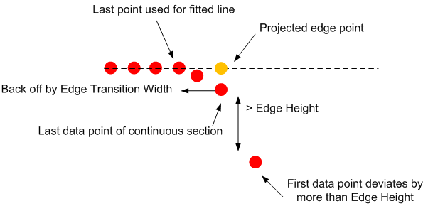
The algorithm then backs off by the value of the Edge Transition Width parameter and uses the data up to the back-off point to create the fitted line and projects the edge point on the line. This step prevents the points near the end of a rounded strip from affecting the height of the strip.